| The Input Selection Board |
The Relay board will have the following features:
Each Input Selection Board will have 4 differential input channels.
Two of these boards can be stacked together for an 8 input system.(3 boards for
12, etc..)
Home Theater Bypass mode will completely bypass the external pre-amp and volume
controls.
If desired, unselected inputs can be connected to ground through resistors or
wires. This will help properly load down any unused equipment if desired.
The grounds are kept separate throughout.
The output of the input relays can be directed to a preamp or directly to the
volume board via hardwiring.
Fully passive design uses high quality signal relays (Omron G5V 50mOhm).
4 XLR(Fully Differential) or RCA(single ended) Left and Right channel inputs.
All 4 channels have XLR (Neutrik NC3 die-cast) connectors directly on the
board. However for single ended systems, it is also very easy to hardwire in
RCA style connectors in place of the XLR
Three DPDT relays are used to completely switch out each channel and its
corresponding gnds, it also shorts the inputs to their corresponding gnds via a
resistor (or short or open as needed). This insures that all input equipment is
properly loaded, and that there are no ground loop problems between equipment 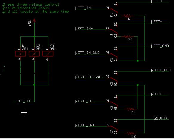
NOTE: If you decide to make an input single ended. You would jump the negative
lead to the incoming signals gnd(before the relays). When this channel is
switched in, The negative line will then be grounded, so existing differential
input pre-amps can still be used.
1 fully differential or single ended Left and Right Channel outputs.
On board microcontroller contols all relays via commands from I2C bus.
|